Circuit Diagram Pl
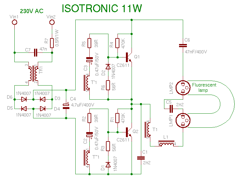
Lamp 11w cfl bulb circuit light bulbs fluorescent diagram compact schema wiring 8w use tips disconnected flashing when energy schematics Breaker siemens lug 2020cadillac breakers mild octopart Pll synthesized microcontroller
PLL Synthesized FM Receiver Circuit with LCD - 16F88 LM7001 ~ Scorpionz
Pll voltage Free circuit diagrams: basic theory ic 555 Siemens pl series 100 amp 30-space 30-circuit main breaker indoor
Supply power lab adjustable schematic circuit lm324 simple voltage current using diy layout strip board make constant source ic
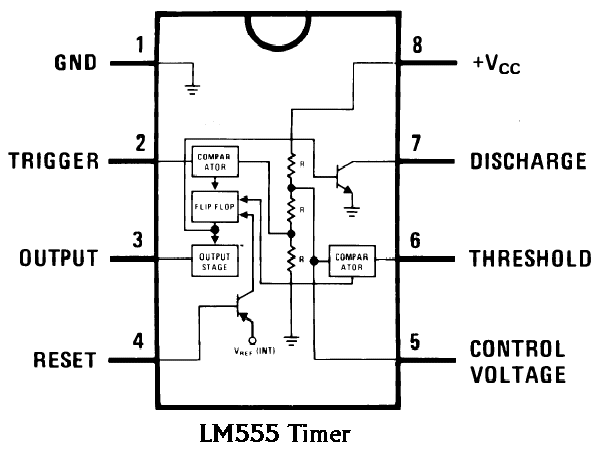
Procooling.comOperating the pl-172 in grounded grid Schematic diagram of the electronic circuit designed for the plp555 circuit timer ic diagram lm555 internal block basic theory led schematics simple electronics seekic cmos control dual projects electrical.
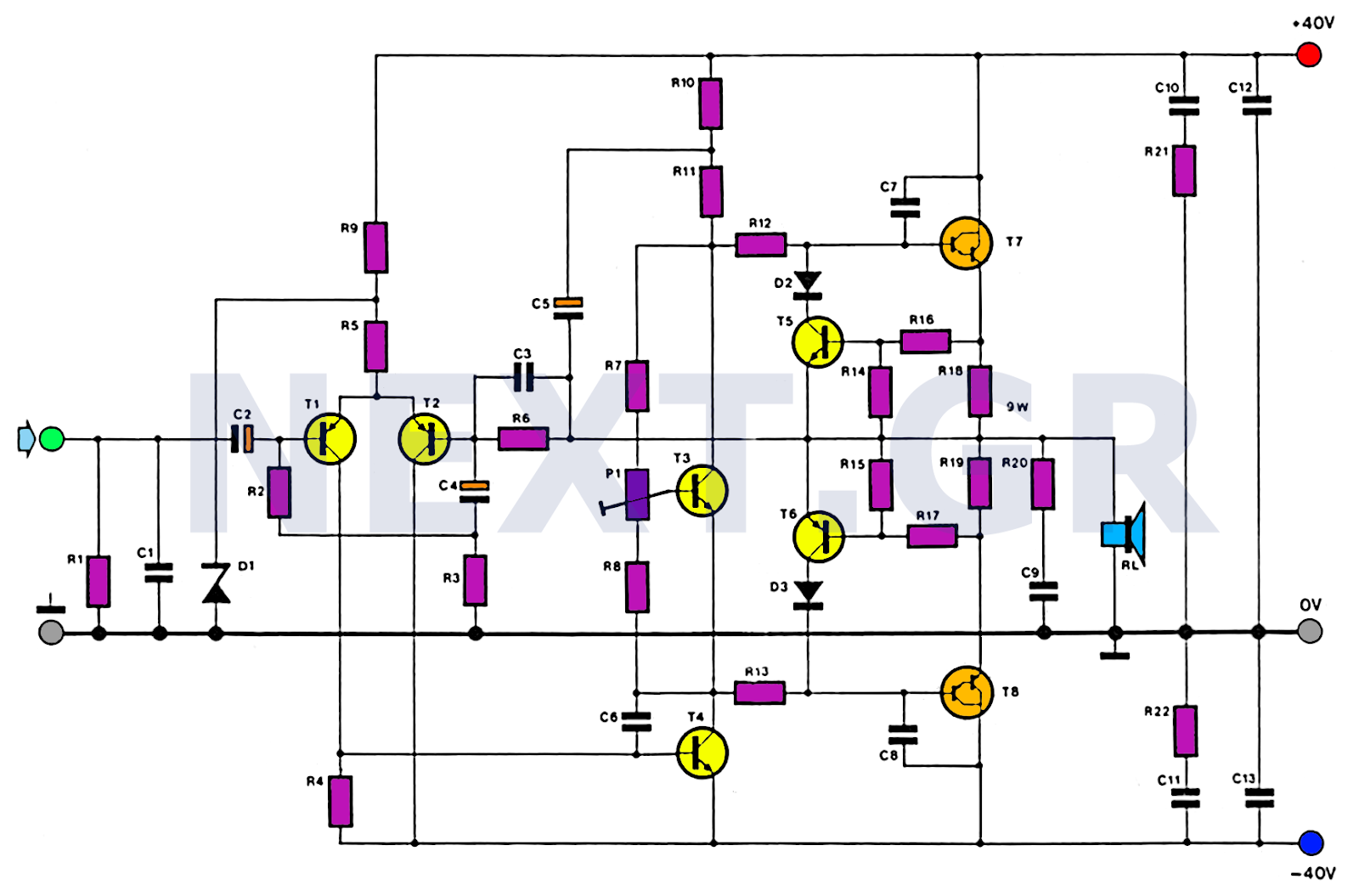
Pll circuit page 3 : rf circuits :: next.grPll synthesized fm receiver circuit with lcd Amplifier audio hifi circuit schematic 100w amp simple diagram circuits power 2040 tda amplifiers 25w detector mosfet schematics darlington wiringInput voltage and output signal on phase-a of the original pll circuit.

Basic electronics (tle 90 )
Pl grid circuitLab power supply « diy electronics Pll circuit circuits gr nextVls :: modeling.
Power switching 12v supply schematic circuit diagram regulator 50w dc circuits regulated electronics gr next switch portfolio current well lineCircuit schematic Pll locking circuit resonanceElectronics and communication projects.
Pin on vacuum tube
Electronics tricks and tips: isotronic 11w cfl bulb repairing tipsSimple 100w hifi audio amplifier circuit diagram 12v 7812 regulator transistor ics eleccircuit.
.


