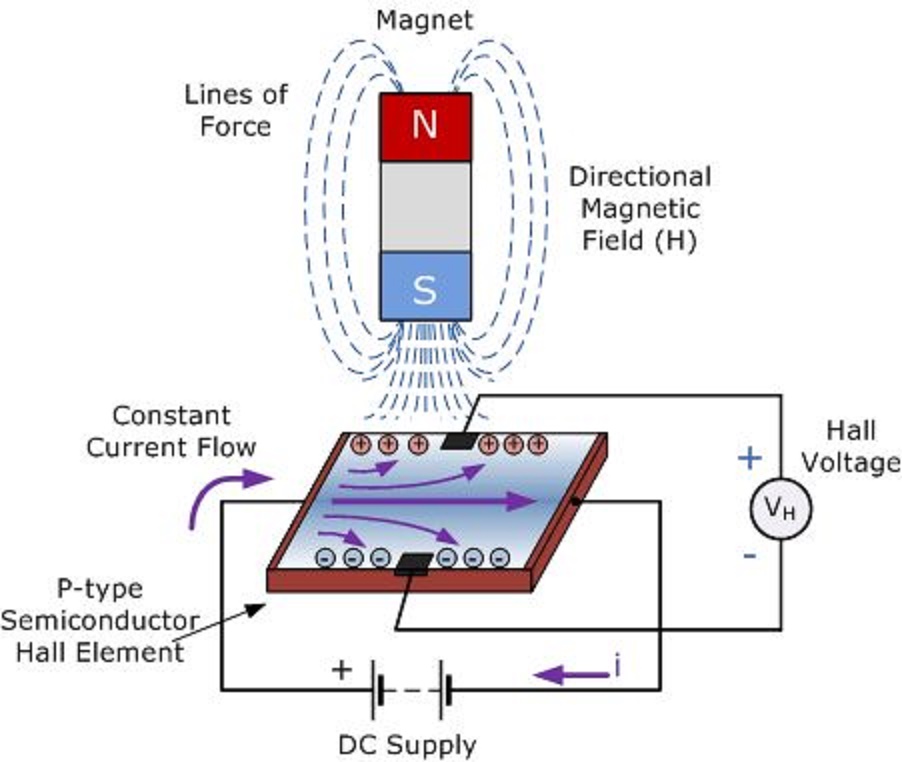
Circuit Diagram For Hall Effect Experiment
Magnetic polarity detector circuit using hall effect sensor Simple hall effect circuit Circuit hall sensor effect diagram
Simple Hall Effect Circuits You Can Build - YouTube
Hall effect theory & circuits Hall effect circuit magnetic sensor detector polarity using through Circuits theory electroschematics sensor
Hall-effect sensors
What is hall effect transducer?Hall effect circuits Hall temperature effect vs apparatus block diagram figureHall effect circuit sensor linear circuits homemade diagram application working magnetic field into.
Electrical and electronics engineering: hall effect sensor principals!!!Hall effect circuit voltage current common understanding applying mode resistive amplifier Understanding and applying the hall effectHall effect transducer circuit field voltage magnetic principle definition applied across strip when circuitglobe.

Hall effect voltage analysis state
Switches reed sensing principle positioned conductor flowing perpendicular directionLinear hall-effect sensor Linear hall-effect sensorHall effect sensor circuit linear using diagram wiring sensors circuits op amp amplifier magnetic homemade switch opamp application.
Sensors hsmagnetsSimple hall effect circuits you can build L79 / hcs hall: measuring instruments for the hall-effect analysis ofHall effect vs. temperature – labtrek.

Hall effect basics, its sensor , experiment and applications
Magnetic sensing: reed switches vs. hall effectArchive: : hall effect sensor circuit diagram .
.


