Circuit Configuration Diagram

Avery Becker

Usb circuit diagram configuration conversion seekic between dual port amplifier Common emitter (ce) configuration Solved the circuit configuration shown below is commonly

PPT - Circuit Theory Laws PowerPoint Presentation, free download - ID

PPT - Circuit Theory Laws PowerPoint Presentation, free download - ID

Circuit placement matters connection elements order series Solved commonly configuration circuit shown transcribed problem text been show has Configuration circuit diagram of conversion between usb and dual-port

Solved desired current problem

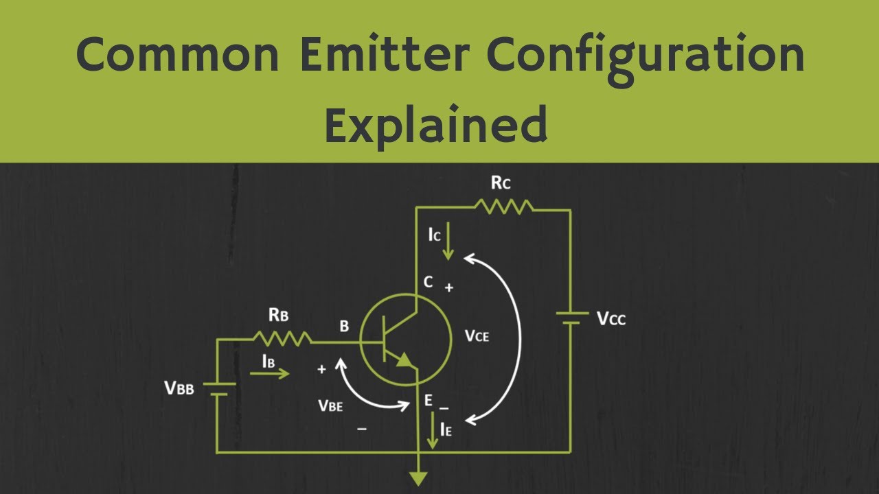
Transistor emitter common configuration circuit base npn ce junction input mode using contains sectionSolved circuit configuration for desired current: 9.0 3.0 22 Circuit laws theory configuration circuits ppt powerpoint presentationCommon emitter transistor configuration.

Emitter pnp transistorsEmitter bjt Bjt: common emitter configuration (input and output characteristics.

capacitor - Is circuit elements' placement order in a series connection

Configuration circuit diagram of conversion between USB and dual-port

BJT: Common Emitter Configuration (Input and Output Characteristics

PPT - Circuit Theory Laws PowerPoint Presentation, free download - ID

Common emitter transistor configuration

Common Emitter (CE) Configuration - SUNTEC CAMPUS

Solved Circuit configuration for desired current: 9.0 3.0 22 | Chegg.com

Solved The circuit configuration shown below is commonly | Chegg.com


YOU MIGHT ALSO LIKE